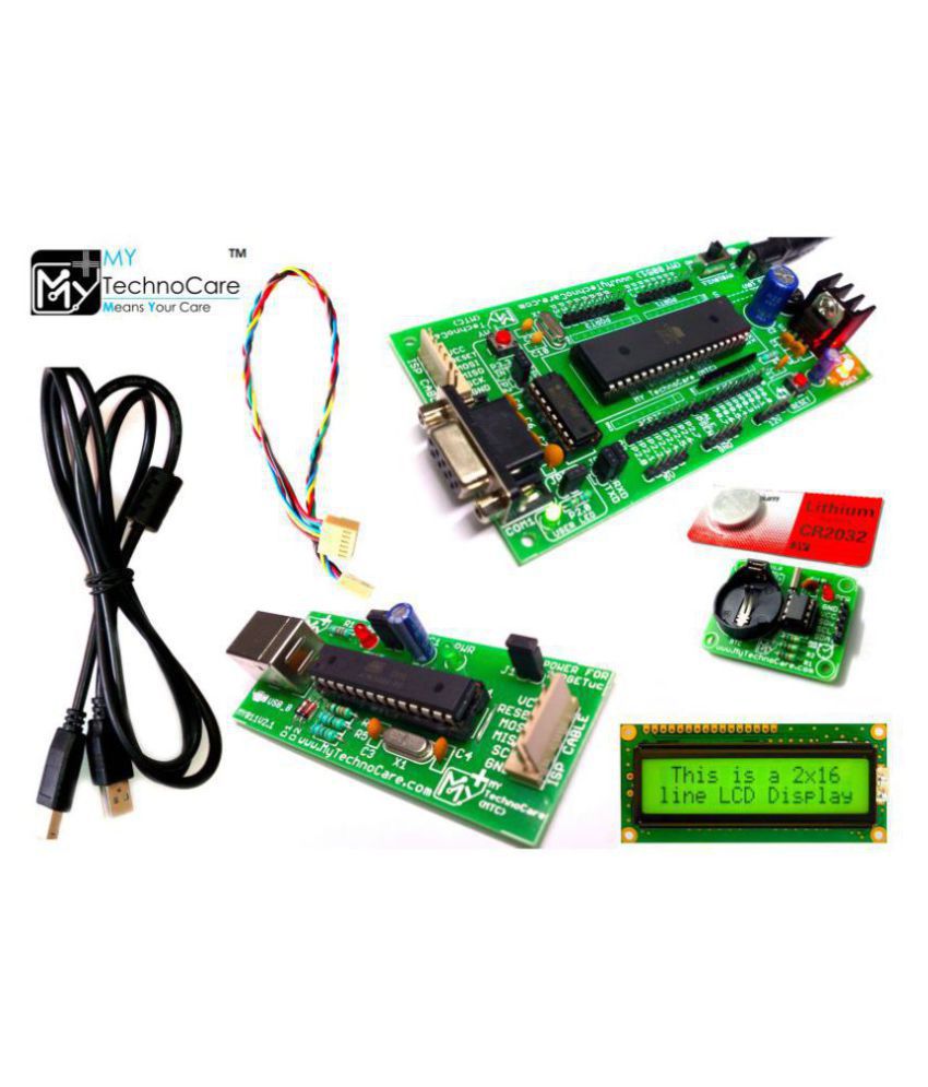
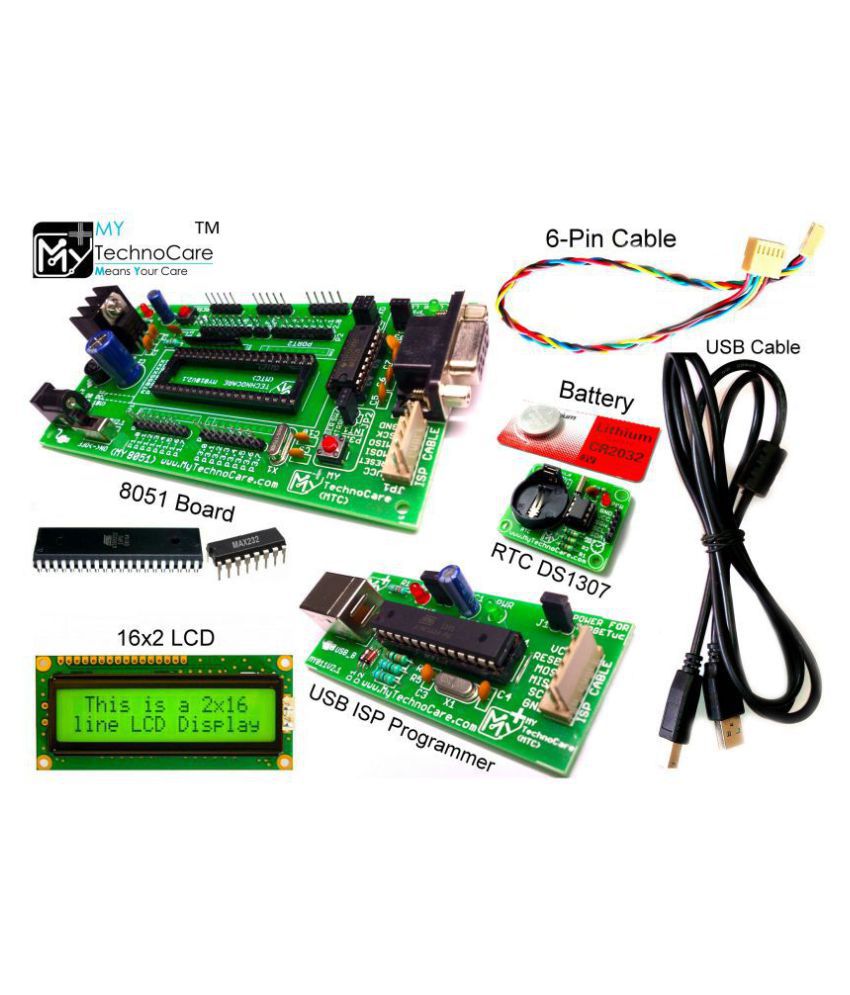
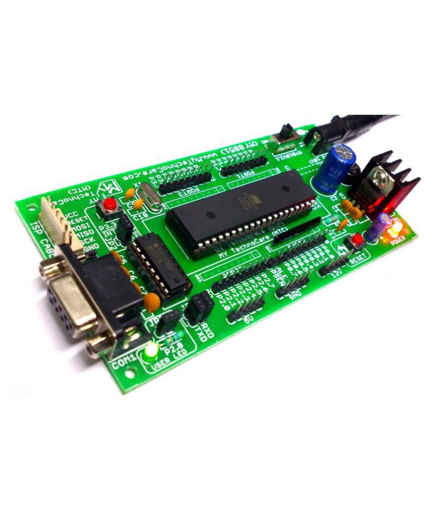
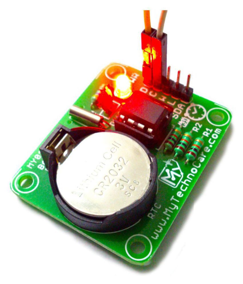
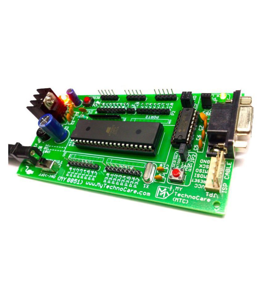
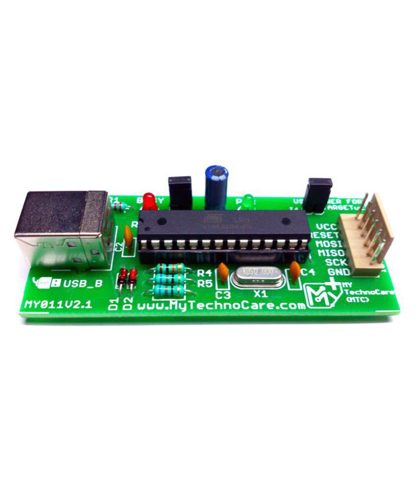
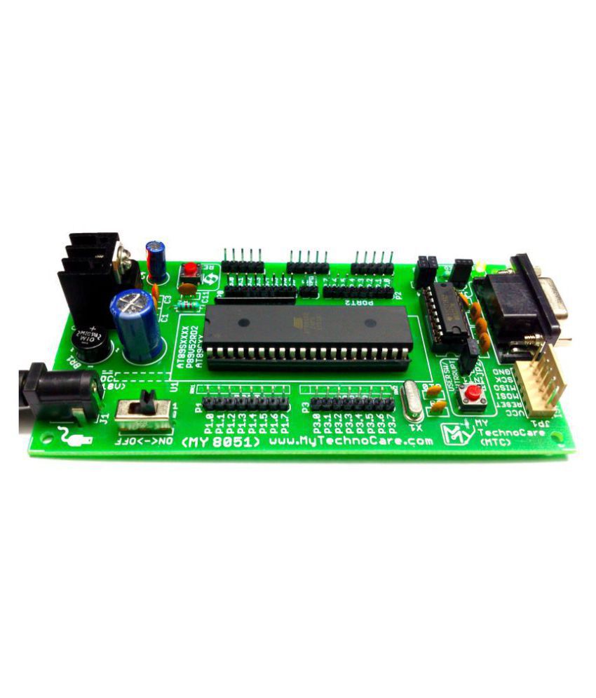
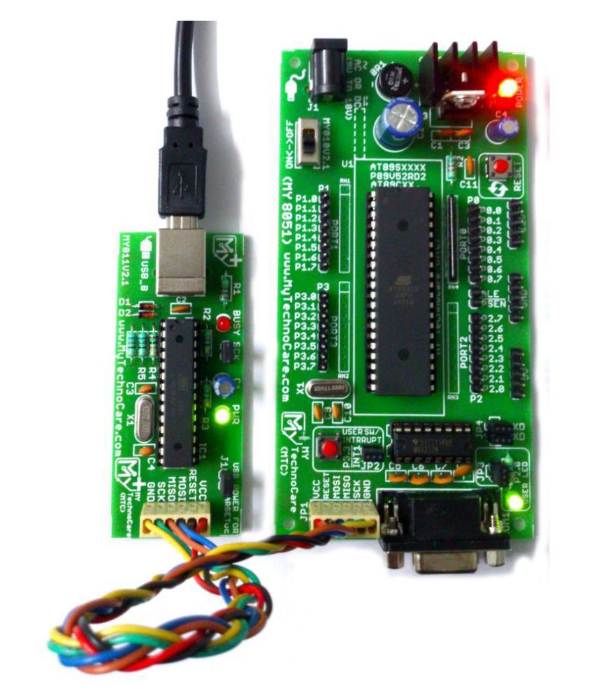
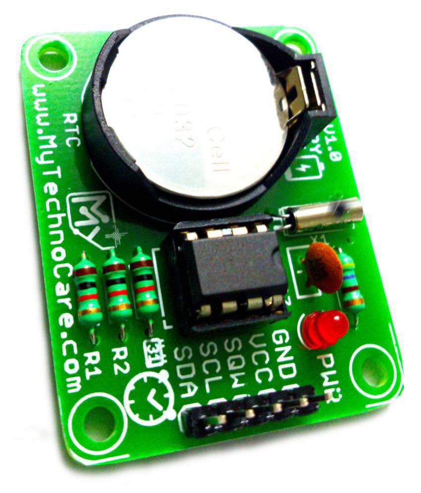
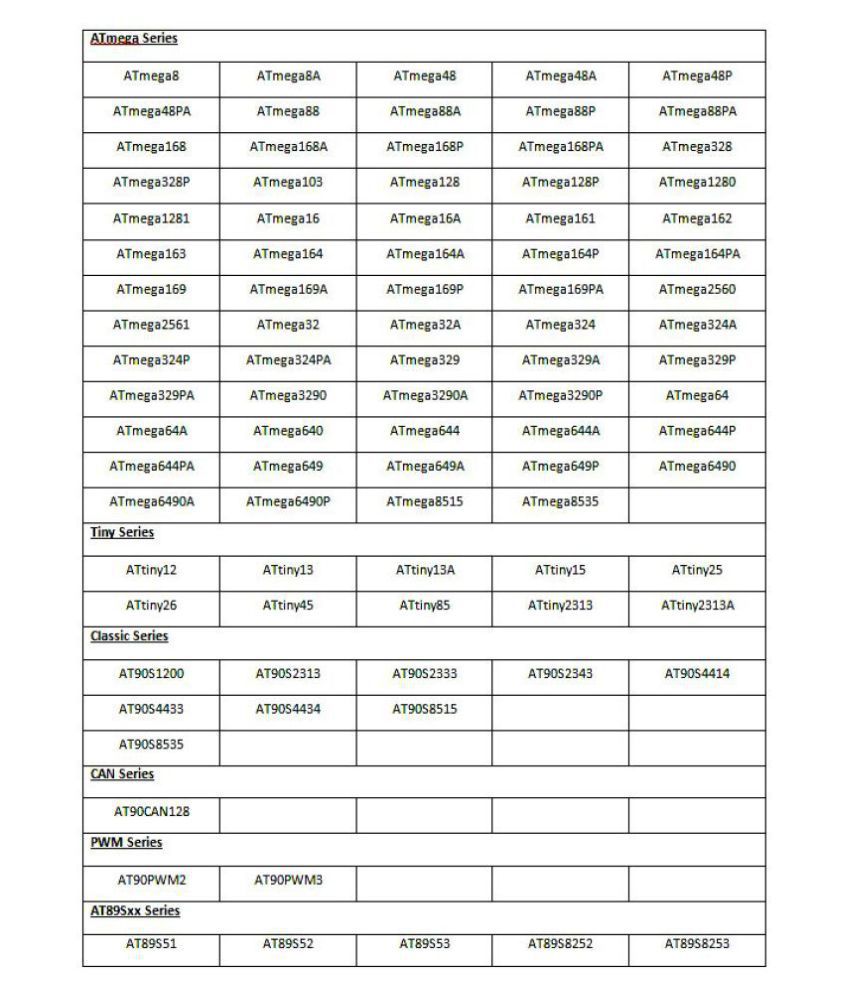
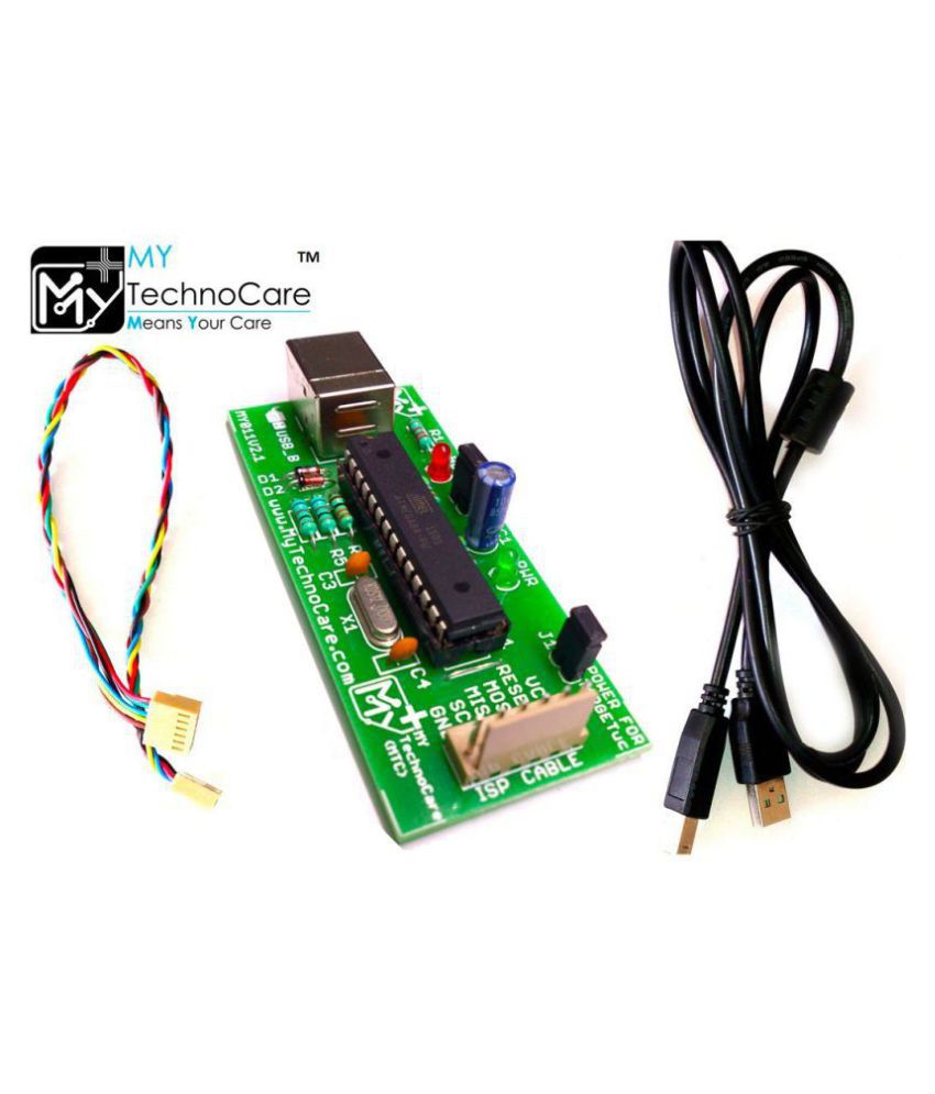
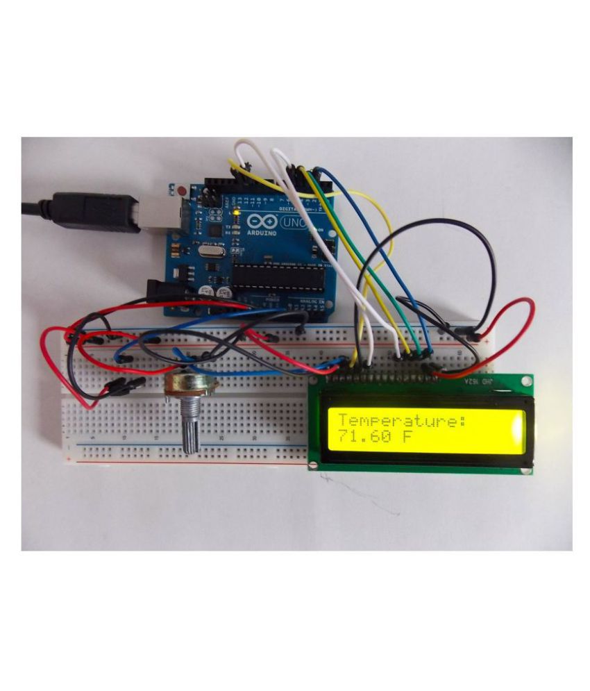
DS1307 RTC Real Time Clock Module, 8051 Microcontroller and Embedded Systems Development Board with 16x2 LCD Display, Atmel AT89S52 IC + RS232 IC | USB ISP Programmer for AVR, 8051/8052 Programming | Electronics Engineering Project Kit. 8051 Development Board with LCD 16×2 Display with Yellow Backlight and USB Programmer have On-Board MAX232 & AT89S52 Microcontroller IC. 8051 Development Board with LCD Project Kit Support AT89S51, AT89S52, P89V51RD2 etc. 40-Pin DIP Chip. USB Programmer can be used for both 8051-AVR IC (2in1).16×2 LCD Display has Yellow Back-light. ABOUT 8051 PROGRAMMER: For How To Program 8051 AVR Microcontroller |How to install driver |Circuit Diagram-Connection| Driver For All Windows OS 64|32-bit (All in 1 RAR file) Download= https://bit.ly/progallinfo | AVR 8051/8052 USB ISP Programmer For Atmel AVR & 8051 Microcontroller With Free USB Cable. Programmer Support many Digital Microcntrollers like (89S51, 89S52, AT89SXX, Classic AT90SXX, CAN Series) & (AVR, ATmega, ATtiny) ATmega 8/328, 16, 32 etc. with the same Programmer. For Supported IC List: SEE Product Images. It is low cost USB based programmer. No need to take out Target Micro controller from the development Board. Programmer will work with variety of Atmel AVR & 8051 microcontroller. It Allows You to Read/Write the Microcontroller Flash, EEPROM, Fuse Bit & Lock Bit. Support Windows OS ( Xp to 10),Mac OS X & Linux. ATmega8 with USBasp Firmware Pre-loaded. SCK Option to Support Targets with Low Clock Speed (<1.5 MHz).5 KB/sec Maximum Write Speed. Programmer can provide 5V supply for Target Microcontroller, so No Need of Any External Supply. Two Status LEDs | Green LED: Power Supply Indicator| RED LED: It is ON While Programmer is Busy.6 pin Polarized ISP Interface for Easy Connection. Supported Software: Progisp, AVRdude, Khazama AVR Programmer | ABOUT 8051 DEVELOPMENT BOARD: If You are Learning Microcontroller Programming & want to make Project based on 8051 microcontroller then This Board will help you. With this board you can Develop & Prototype with any of 8051(AT89S51, AT89S52, P89V51RD2, AT89Cxx) 40 pin microcontrollers.1.5 Amp Bridge Rectifiers allow this board to be Powered with both AC & DC power supply adapters. It RS232 Serial port for flashing like P89V51RD2 (NXP) microcontrollers & also use for interfacing GSM module, GPS Module, RFID Module. There is 5V, 12V, GND Power bus which allow to Power external Peripherals module. FEATURES of 8051 Board: DIP 40 Pin Microcontroller IC Socket For Easy Insert/Removal of Microcontroller IC.RS232 Interface Circuit for Easy Communication with PC & other Serial Devices(GPS modules, GSM Modems, etc.).High quality FR-4(1.6 mm) PCB. On-Board bridge rectifier so that board can accept both AC and DC Input voltages Power supply .Recommended Input Voltage: 9-12V.Min-Max Input Voltage: 9-18V.On-Board 5 mm Power Plug-in DC Jack. On-Board 5V regulator (LM7805) circuit. On-Board Power ON - OFF switch. On-Board power indication RED LED. On-Board GREEN USER LED connected to P2.0 through jumper JP3.On-Board Input User Switch P3.3 through jumper JP2.On-Board Input External Interrupt Switch (INT1) at P3.3 through jumper JP2.On-board Quartz Crystal 11.05892 MHz. Port Extensions for all PORT with Detailed Pin Labeling for Easy Identification of Pin. External Pull-Up resistors for Port 0.On-board ISP connector for loading HEX file into Microcontroller like AT89S51/52 etc. Vcc bus (5V and 12V) & GND bus provided to Give POWER Supply to the External Peripheral. Four 3mm mounting hole for easy mounting. On-board Reset button. Dimensions: 12cm x 6.4cm. ABOUT 16x2 LCD DISPLAY: 16×2 LCD Display Support mostly All Digital Microcontroller such as Arduino, 8051, PIC, AVR, ARM, MSP, COP8, STM, Raspberry Pi etc. First of all 16×2 LCD is a basic 16 character by 2 line display Yellow/Green Back light. Utilizes the extremely most common HD44780 parallel interface chipset (datasheet). Even more it has JHD162A Compatible Pin-out Diagram, so Command Interface code is freely available. Finally you will need 7 general I/O pins (If use in 4-bit Mode) to interface to this LCD screen. It also Includes LED back-light. Learn How To Interface 8051 Development Board with LCD 16×2 Display using 8051/AVR USB Programmer for Burn/Flash Hex File into Atmel AT89S52 Microcontroller. | FEATURES of 16×2 Display LCD: Commonly Used in: Student Project, Collage, copiers, fax machines, laser printers, industrial test equipment, networking equipment such as routers and storage devices | LCD display module with Green/Yellow Backlight | SIZE: 16×2 (2 Rows and 16 Characters per Row) | 16x2 LCD Can display 2-lines X 16-characters | It Operate with 5V DC | Wide viewing angle and high contrast | Built-in industry standard HD44780 equivalent LCD controller | LCM type: Characters. | ABOUT DS1307 REAL TIME CLOCK: DS1307 RTC Module is I2C Real Time Clock Module with 56 Byte NV RAM | DS1307 RTC Module Support All Digital Microcontroller such as Arduino, 8051, PIC, AVR, ARM, MSP, COP8, STM, Raspberry Pi etc. |This is the DS1307 Real Time Clock (RTC) Module, this small breakout board that uses the most popular DS1307 to keep track of the current year, month, day as well as the current time. The module comes fully assembled and includes a small Lithium coin cell battery that will run the RTC for a minimum of 9 years without an external 5V Power supply. The DS1307 RTC is accessed via I2C Protocol | Features of Real Time Clock DS1307 Board: | Two wire I2C interface, (hh : mm : ss) Hour : Minutes : Seconds AM/PM, (DD/MM/YYYY) Day, Month, Year | Leap year Compensation, Accurate Calendar up to year 2100 | Battery Backup Included, 3 Volt Li (Lithium) Coin Battery | 1Hz output pin | 5 Volt Power Supply | 56 Bytes of Non-volatile Memory Available to User | Plugs into any breadboard, or You can use wires | On board power indication RED LED | Four Mounting Holes 3.0 mm for Easy Mounting | Dimensions: 43 mm x 34.5 mm | Download User Manual of DS1307 = https://bit.ly/DS1307rtc, Download Circuit Diagram of DS1307 = https://bit.ly/ds1307CKT | Package Contents : 1 x 8051 Development Board With Onboard MAX232 & AT89S52 IC, 1 x USB ISP Programmer, 1 x 6-pin Polarized Cable, 1 x USB A to B Cable, 1 x LCD 16×2 with Yellow/Green Backlight, 1 x RTC Module with DS1307 | Have any Queries; Please Contact Us mytechnocare.info@gmail.com or MyTechnoCare Website. | Download Programmer Driver & Manual = https://bit.ly/progallinfo and 8051 Kit Manual = https://bit.ly/8051kitdata NOTE: POWER SUPPLY Adapter IS NOT Included WITH THIS ITEM.
 Download App